


Practical EMC Design for Modern Engineers


Downloads
| REO2025-12-Bring-the-EMI-Noise.docx ( DOCX 245KB) |
| Figure-1-–-REO-Choke-Winding.png ( PNG 1067KB) |
| Figure-2-REO-High-Ingress-Choke-scaled.jpg ( JPG 257KB) |
| Figure-3-EMC-Test-Data.png ( PNG 248KB) |
| Figure-4-–-REO-DC-Power-Supplies.png ( PNG 5690KB) |
Practical EMC Design for Modern Engineers
Electromagnetic interference (EMI) doesn’t have to be feared but needs to be understood. It’s a recurring roadblock for many design engineers: countless PCB revisions, last-minute fixes, and filters added more in hope than confidence. But EMI isn’t magic—it’s physics. With the right approach, simulation tools, and a solid grasp of the standards, engineers can bring the noise—and then filter it—with precision, efficiency, and compliance in mind.
This article examines the practical aspects of EMI and EMC, from selecting the appropriate filter topology to understanding how environmental conditions, cable runs, and real-world nonlinearity impact performance. We also highlight how companies with specialist expertise in EMC filtering can support robust, standards-compliant product development.
From Interference to Compliance: Understanding the EMI Challenge
EMI is unwanted electrical noise that disrupts the intended operation of devices, systems, and communications. In contrast, electromagnetic compatibility (EMC) is the ability of a product to function properly without generating or being affected by that interference.
Achieving EMC compliance means addressing emissions and immunity; filters are often the frontline solution. But filtering isn’t just about adding a capacitor here or an inductor there — it’s about understanding how interference propagates and how to block it effectively.
Filtering 101: Topologies That Tame the Noise
Filters are built from passive components — inductors, capacitors, and resistors — arranged to attenuate unwanted signals while preserving the useful ones. Standard filter configurations include:
- LC filters: Ideal for suppressing high-frequency noise.
- RC filters: Useful in low-power or signal-line applications.
- Pi (C-L-C) and T (L-C-L) filters: Provide increased attenuation and flexibility.
- Common-mode chokes: Target common-mode interference but offer differential-mode attenuation due to leakage inductance.
Designers must consider the filter type and how it integrates with the system, including impedance, expected frequencies, and physical layout. Using the wrong filter or applying it incorrectly can do more harm than good, amplifying rather than attenuating noise.
Differential vs Common Mode: Dual Fronts in EMI Defence
Most real-world EMI problems involve both differential-mode and common-mode noise. Differential-mode noise flows between conductors in opposite directions, typically generated by switching components. On the other hand, common-mode noise appears identically on both conductors relative to a reference, such as ground or chassis.
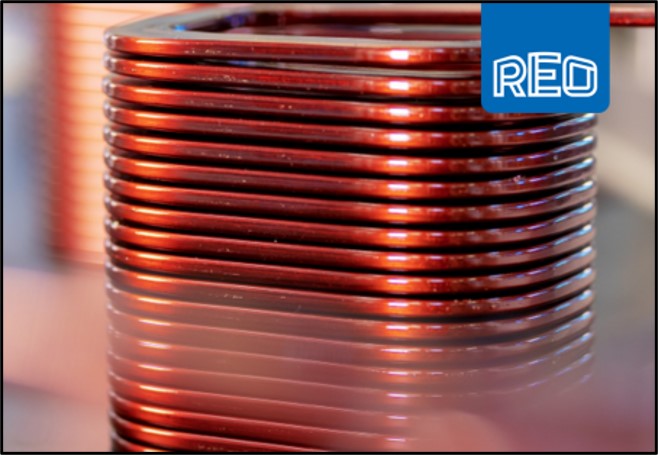
An effective EMI strategy filters both. Common-mode chokes, for example, are invaluable in addressing common—mode emissions, especially when paired with capacitors to ground. Meanwhile, series inductors or resistors may be better suited for differential suppression. Figure 1 – REO Choke Coil
Standards in the Signal Chain: What Engineers Need to Know
A wide range of EN standards apply depending on the product category and operating environment to ensure EMC performance is not just good practice but legally mandated. For example:
- EN 61000-6-4 – Generic emission standards for industrial environments
- EN 61000-6-2 – Generic immunity standards for industrial use
- EN 50121 series – EMC standards for railway equipment
These standards define acceptable emissions levels, and the tests required to demonstrate compliance. Filter design plays a crucial role in meeting the conducted and radiated emissions criteria, particularly in sectors where regulatory scrutiny is stringent.
The Real World Isn’t Ideal: Nonlinearity and Environmental Effects
Theory can only go so far. In real-world designs, nonlinear effects begin to show, particularly as switching frequencies increase and power densities rise:
- The dielectric behaviour of capacitors changes with temperature and frequency.
- Magnetic cores can saturate or lose permeability under high currents.
- Leakage inductance and parasitic capacitance can introduce unexpected resonances.
What works on a datasheet might not work in a test chamber. That’s why experienced engineers now turn to simulation and practical testing earlier in development.
Simulate First, Filter Once
Modern simulation tools — especially those based on SPICE — enable engineers to model filter behaviour before committing to hardware. With parasitics and nonlinearities factored in, SPICE simulations offer a reliable window into:
- Frequency response and attenuation
- Impedance matching
- Susceptibility to resonance
- EMI mitigation across a broad frequency range
Simulations won’t replace EMC testing, but they can significantly reduce the number of physical iterations needed — and improve the likelihood of a first-time test pass.
Filtering Beyond the Schematic: When Installation Gets Tough
Specific design environments make filtering incredibly challenging. That’s where practical considerations come into play — ones that extend beyond the circuit diagram. For example:
- IP-Rated Filters for Harsh Environments
Dust, moisture, vibration, and heat are all enemies of consistent filter performance. High IP-rated filters (e.g., IP54, IP65, IP67) are essential in rail, marine, or outdoor applications. These robust enclosures protect the filter components without compromising EMC performance. Figure 2 – High IP-rated EMC filter
- Water Cooling for High Power Density
Traditional air cooling is often insufficient for high-power inverters, EV chargers, or industrial drives. In these scenarios, water-cooled filters and chokes can keep systems compact and efficient while maintaining performance under thermal stress.
- Filters for Long Cable Runs
Cables can act as unintentional antennas, picking up or radiating EMI. Specialised filters for long cable runs help attenuate common- and differential-mode noise close to the source or load while also addressing potential reflections and impedance mismatches. Figure 3 – EMC Results for Long Cables
- Wide Bandgap Devices and EMC: The GaN and SiC Effect
The growing adoption of Gallium Nitride (GaN) and Silicon Carbide (SiC) semiconductors in power electronics is transforming the landscape of EMC design. These wide bandgap devices offer faster switching speeds, higher efficiency, and reduced losses compared to traditional silicon, essential for next-generation power supplies, inverters, and EV chargers.
However, these benefits come with a trade-off: higher di/dt and dv/dt switching rates, significantly increasing the potential for electromagnetic emissions.
Key implications for EMC design include:
- More aggressive conducted and radiated noise, particularly in the MHz range.
- Optimised PCB layout, minimising loop areas and parasitic capacitances.
- Filters with higher frequency attenuation capability often require advanced materials and compact, low-inductance configurations.
- Increased importance of shielding, grounding, and impedance control across the entire system.
Designers working with GaN and SiC must often adopt a more holistic EMC strategy, combining high-speed layout techniques with appropriately specified input/output filters. In many cases, pre-compliance testing and simulation become essential tools for validating designs early and avoiding costly redesigns down the line.
Partnering Up: When to Call in the Experts
While in-house teams can often manage standard filtering needs, working with specialist EMC filter manufacturers benefits specific applications. These companies bring product expertise and a deep understanding of the standards and real-world installation scenarios.
A good filter partner can offer:
- Pre-certified filters aligned with EN standards
- Custom filter solutions tailored to high IP, thermal, or footprint constraints
- Simulation support and datasheets with real-world performance metrics
- Consultation on placement, grounding, and integration with other EMC mitigation measures
This is especially useful for companies operating in highly regulated sectors, such as rail, medical, and energy, where compliance and reliability are business-critical.
Conclusion: Make Noise, But Make It Compliant
EMI isn’t going away; faster switching, denser electronics, and more interconnected devices mean it’s becoming more challenging. But with the right strategy—combining intelligent filter design, accurate simulation, and practical implementation—noise becomes something you can control, not fear.
Whether you’re designing a drive system for a wind turbine, an EV charger, or a safety-critical rail component, EMC filtering is no longer an afterthought. It’s vital to deliver reliable, market-ready products that meet both performance expectations and regulatory demands. Figure 4 – REO DC Power Supplies
To find more information on REO filters, please visit https://www.reo.co.uk/types/filters/
So go ahead — bring the noise. Just make sure you know how to filter it.